Modern engines don’t run on fuel and spark alone. They run on data.
Behind every smooth idle, clean acceleration, and acceptable emissions reading is a network of sensors constantly feeding information to the engine control unit (ECU). The ECU doesn’t guess—it calculates. And it can only calculate correctly if the sensors give it accurate information.
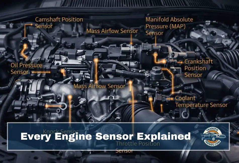
This guide explains all the major engine sensors, grouped logically so they’re easier to understand. For each sensor, we’ll cover:
- What it does
- How it works (in simple terms)
- Where it’s located
- What happens when it fails
How Engine Sensors Are Organized
Although there are many sensors, most fall into five functional categories:
- Position sensors
- Airflow and pressure sensors
- Temperature sensors
- Air–fuel ratio and emissions sensors
- Safety and protection sensors
Let’s start at the foundation.
Position Sensors
- Telling the ECU Where Everything Is
- Crankshaft Position Sensor (CKP)
What it does:
Tells the ECU the exact position and speed of the crankshaft.
Why it matters:
The position of the crankshaft directly determines piston position. Without this data, the ECU cannot time fuel injection or ignition.
How it works:
Most crank sensors are either:
- Hall-effect sensors (3 wires)
- Variable reluctance (VR) sensors (2 wires)
Both read a trigger wheel made of ferrous metal. The wheel has one or more missing teeth. When a missing tooth passes the sensor, the signal changes. The ECU uses this change as a reference point.
By counting teeth and measuring time between them, the ECU calculates:
- Engine position
- Engine speed (RPM)
Where it’s located:
Very close to the crankshaft, usually at:
- The crank pulley
- Timing gear
- Flywheel
Failure symptoms:
- Engine will not start
- Engine starts briefly, then stalls
- Misfires, rough running, poor acceleration
1. Camshaft Position Sensor (CMP)
What it does:
Tells the ECU the position of the camshaft.
Why it matters:
While an engine can technically run with only a crank sensor, the cam sensor allows:
- Sequential fuel injection
- Cylinder-specific ignition timing
- Knock control per cylinder
How it works:
Same principle as the crank sensor, but with a smaller trigger wheel and fewer teeth.
Where it’s located:
Mounted on or near the camshaft:
- On the valve cover
- At the front or rear of the camshaft
Failure symptoms:
- No-start condition
- Rough running
- Loss of power
2. Throttle Position Sensor (TPS)
What it does:
Measures how far the throttle plate is opened.
Why it matters:
Throttle position tells the ECU how much load the driver is demanding.
How it works:
Older TPS units used variable resistors. Modern ones use non-contact sensors (Hall-effect or magnetic). The sensor converts throttle angle into a voltage signal.
Where it’s located:
Directly on the throttle body.
Failure symptoms:
- Unpredictable acceleration
- Poor throttle response
- High or unstable idle
- Difficulty starting
Airflow and Pressure Sensors
- Measuring How Much Air the Engine Is Breathing
- Mass Air Flow Sensor (MAF)
What it does:
Measures the mass of air entering the engine.
Why it matters:
Fuel delivery must match air quantity for proper combustion.
How it works:
Uses a heated wire or film. Incoming air cools the element. The ECU measures how much energy is needed to keep it hot and calculates airflow.
Where it’s located:
After the air filter, before the throttle body.
Failure symptoms:
- Rough idle
- Hesitation
- Poor fuel economy
- Stalling
1. Air Flow Meter (AFM)
What it does:
Performs the same function as a MAF but mechanically.
How it works:
Incoming air pushes against a flap connected to a variable resistor.
Where it’s located:
Near or after the air filter.
Failure symptoms:
Same as a failing MAF.
2. Manifold Absolute Pressure Sensor (MAP)
What it does:
Measures pressure inside the intake manifold.
Why it matters:
The ECU calculates airflow indirectly based on pressure.
How it works:
Uses a silicon diaphragm with piezoelectric elements. Pressure flexes the membrane, changing electrical output.
Where it’s located:
Mounted directly on the intake manifold.
Failure symptoms:
- Rough running
- Poor acceleration
- Incorrect fueling
Pressure Sensors
- Protecting the Engine From Damage
- Oil Pressure Sensor
What it does:
Monitors engine oil pressure.
Why it matters:
Low oil pressure causes catastrophic engine damage.
How it works:
Either:
- A pressure transducer (analog signal)
- A simple on/off switch (warning light only)
Where it’s located:
On the engine block, often near the oil filter.
Failure symptoms:
- False oil pressure warnings
- Limp mode
- Engine refusing to start
1. Fuel Pressure Sensor
What it does:
Measures fuel pressure in the fuel rail.
Why it matters:
Injector timing depends on fuel pressure.
How it works:
Pressure transducer calibrated for fuel system pressures.
Where it’s located:
Mounted directly on the fuel rail.
Failure symptoms:
- Hard starting
- Poor acceleration
- Reduced fuel economy
Temperature Sensors
- Correcting Fuel and Protecting Components
- Intake Air Temperature Sensor (IAT)
What it does:
Measures the temperature of incoming air.
Why it matters:
Air density changes with temperature.
How it works:
A thermistor whose resistance changes with temperature.
Where it’s located:
- Integrated into the MAF
- Or in the intake duct near the throttle body
Failure symptoms:
- Mild surging
- Rough idle
- Occasional stalling
1. Coolant Temperature Sensor (ECT)
What it does:
Tells the ECU how warm the engine is.
Why it matters:
Cold engines need more fuel. Hot engines need protection.
Where it’s located:
Near the thermostat or coolant passages.
Failure symptoms:
- Rich or lean running
- Poor mileage
- Overheating protection triggering incorrectly
2. Fuel Temperature Sensor
What it does:
Measures fuel temperature.
Why it matters:
Fuel density changes with temperature.
Where it’s located:
Usually inside the fuel tank or fuel pump module.
Failure symptoms:
Often subtle, may affect emissions or efficiency.
3. Oil Temperature Sensor
What it does:
Monitors oil temperature.
Why it matters:
Overheated oil loses viscosity and lubrication ability.
Where it’s located:
Engine block, cylinder head, or integrated with oil level sensor.
Failure symptoms:
- Incorrect limp mode activation
- Missed overheating warnings
Air–Fuel Ratio and Emissions Sensors
- Keeping Combustion Clean and Efficient
- Oxygen Sensor (O₂)
What it does:
Measures oxygen in exhaust gases.
Why it matters:
Allows ECU to control air–fuel ratio.
Types:
- Narrowband: rich vs lean
- Wideband: precise AFR measurement
Where it’s located:
- Upstream (before catalytic converter)
- Downstream (after catalytic converter)
Failure symptoms:
- Poor fuel economy
- Rough running
- Emissions test failure
1. Exhaust Gas Temperature Sensor (EGT)
What it does:
Measures exhaust gas temperature.
Why it matters:
Protects turbochargers, catalytic converters, and diesel aftertreatment systems.
Where it’s located:
- Exhaust manifold
- After diesel particulate filter (DPF)
Failure symptoms:
- Frequent regeneration cycles (diesels)
- Reduced performance
2. NOx Sensor
What it does:
Measures nitrogen oxide emissions.
Why it matters:
Verifies proper operation of SCR systems.
Where it’s located:
Before and after the SCR catalyst.
Failure symptoms:
- Limp mode
- Poor mileage
- Emissions warnings
Safety Sensors
- Preventing Engine Damage
- Knock Sensor
What it does:
Detects abnormal combustion (knock).
Why it matters:
Knock can destroy engines.
How it works:
Piezoelectric sensor tuned to knock frequencies.
Where it’s located:
Bolted directly to the engine block.
Failure symptoms:
- Often none
- On newer cars: limp mode